SoltarinE: Solar Charging Station for Farm Machinery
A tracker that keeps a panel on the sun. Two axes of motion on a farm-fabricated frame, controlled by a microcontroller, and published in E3S Web of Conferences with the wider team.
Electric farm machinery needs off-grid field power. A panel fixed at one angle is only square to the sun for a brief window each day; morning and late afternoon sunlight arrive at steep oblique angles, causing substantial solar irradiance loss.
The fix is mechanical before it is electrical: move the panel on two independent axes so azimuth correction is not sacrificed for elevation. That required a frame fabricated from stock workshop steel, linear actuators sized for both wind load and panel mass, and a straightforward microcontroller routine designed to be serviceable directly in the field.
The 3D model and assembly for the two-axis tracker, the actuator mounting and travel, and the microcontroller control that steps the panel through the day.
Panel and battery sizing, charge controller selection, the field siting, and the writing of the conference paper.
Solar panel, charge controller, battery bank, linear actuators, and the microcontroller board. Off-the-shelf, not designed here.
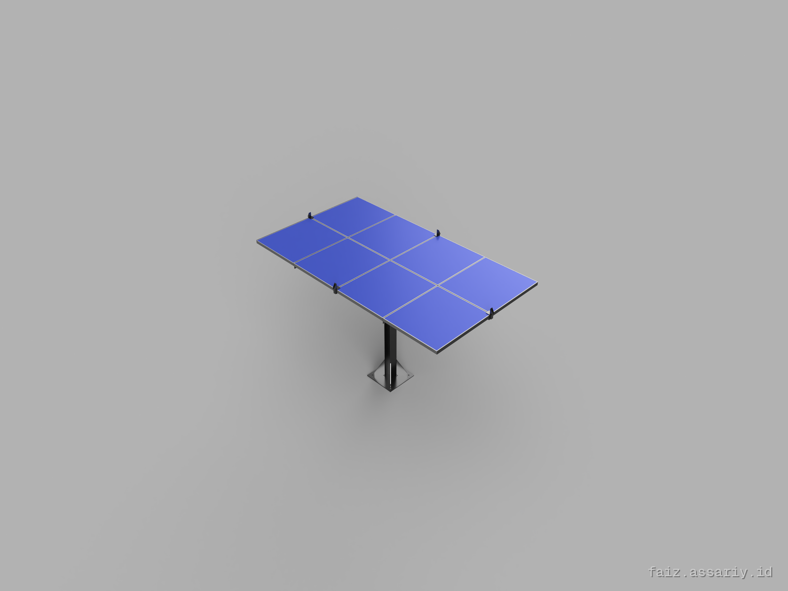
One vertical axis for azimuth, one horizontal axis for elevation, both driven from the base so the panel carries no actuator mass on its own frame.
Elevation and azimuth limits set in CAD first, because an actuator that runs past its stop breaks the frame, not just the linkage.
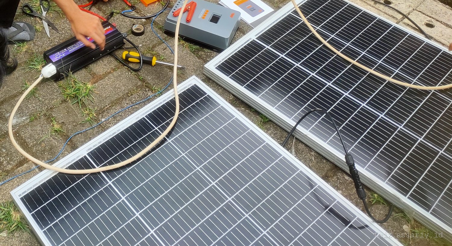
Frame assembled, charge controller and panel wiring laid out, then the control loop exercised through a full day of travel.
| Claim | Method and conditions | Result | Known shortfall and next step |
|---|---|---|---|
| Two-axis travel holds the panel on the sun | Azimuth and elevation limits modelled in CAD, then exercised through a full day of travel on the built frame. | Works | No solarimeter was used, so the gain over a fixed panel is not measured. Any efficiency claim here would be an estimate, so none is made. |
| Actuator control from the microcontroller | Step commands through the day, with limit checks at both ends of travel. | Works | Open loop. There is no feedback on actual panel angle, so a slipping linkage is invisible to the controller. |
| Charging the machinery | Charge controller and panel wired and run on the built station. | Works | Charge energy per day was not logged with a meter. Rev 2 adds a shunt and a daily log. |
What is absent from this table is absent from the record. The paper documents the design and build; it does not report an instrumented efficiency comparison.
What I would change. The control loop is open-loop. A low-cost angle encoder on the elevation axis would have made the entire station verifiable, turning a qualitative orientation claim into hard angular telemetry.
What the work taught. Tracker design is a stiffness problem before it is a control problem: a frame that flexes under wind gusts places the panel somewhere other than where the kinematic model predicts.
What to test on day one. A full-day tracking cycle with the panel loaded and a current shunt logging energy output, so the primary metric is delivered Watt-hours, not opinion.